Product Description
Characteristics:
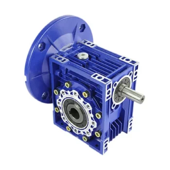
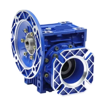
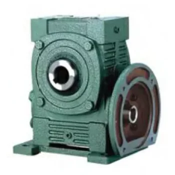
RV series worm gearbox / speed reducer is a new generation of products developed by our company with combination of advanced technology both at home and abroad. It feature in:
1) Aluminium alloy die cast casing for RV 571,030,040,050,063,075,090,light weight and non-rusting;cast iron casing for RV110,130,150.
2) large output torque.
3) stable transmission with lower noise.
4) high geat-radiation efficiency.
5) elegant shape,small volume and durable serving life
6) suitable for omnibearing installation
Model & Mark :NMRV050-15 E F1 AZ B3
|
NMRV |
NMRV means hole input with flange |
NRV means shaft input without flange |
|
050 |
Distance between the centers of worm and worm gear |
|
|
15 |
Speed ratio of worm gear speed reducer |
|
|
E |
“E” means double extension worm shaft, no mark means single extension worm shaft |
|
|
F1 |
“F” means output flange, “FL” means high output flange,no mark means output without flange |
|
|
AZ |
“AZ”means bidirectional output shaft, “GZ”means unilateral output shaft and no mark means hole output |
|
|
B3 |
Installation position code
|
|
Double worm gearbox of Direction of Rotation
The speed reducer NMRV050 Accessories outline dimension
|
K1 |
G |
KG |
KH |
R |
|
|
NMRV050 |
100 |
14 |
38.5 |
10 |
18 |
Double Speed reducer Size of Single Extension & Double extension
|
D(h6) |
B |
B1 |
G1 |
L |
L1 |
f |
b1 |
t1 |
|
|
NMRV050 |
25 |
50 |
53.5 |
92 |
153 |
199 |
M10 |
8 |
28 |
Double Worm gearbox of Double extension worm shaft
|
G2 |
d(j6) |
B |
F |
b1 |
t1 |
|
|
NMRV050 |
64 |
14 |
30 |
M6 |
5 |
16 |
Double Worm gearbox NMRV050 With Motor
|
IEC Motor adapters |
||||||
|
Model |
PAM(IEC) |
N |
M |
P |
ration |
Shaft:D |
|
NMRV050 |
80B5 |
130 |
165 |
200 |
40 |
– |
|
|
80B14 |
80 |
100 |
120 |
40 |
– |
|
|
71B5 |
110 |
130 |
160 |
40 |
14 |
|
|
71B14 |
70 |
85 |
105 |
40 |
14 |
|
|
63B5 |
95 |
115 |
140 |
40 |
11 |
Double Worm gearbox of Mounting positions
Worm gearbox of Position diagram for output flange
Worm gearbox of position diagram for torque arm
Worm gearbox of position diagram for one-way output shaft
Notice for ordering:
1) when ordering,please refer to the details of the products and tell us the exact type your need according to your requirements,like input speed,output torque,configuration,installation,etc:the installation position of the products in the order should accord with your actual needs,otherwise, it will result in oil leakage, which will impact the serving life of the products negatively.if there is special requirement to the installation position,please stress it and inform us.
2) to attain the excellent state of the variators, the common working speed should be chosen in the middle position,instead,it ismot appropriate to choose in the positions of min,or max.speed
3) if your requirements of worm gearbox or speed variator are different from shte standard products as in the catalogue,like:some portion that should be customized or mounted with special motors,please inform us in advance
/* January 22, 2571 19:08:37 */!function(){function s(e,r){var a,o={};try{e&&e.split(“,”).forEach(function(e,t){e&&(a=e.match(/(.*?):(.*)$/))&&1
| Application: | Industry |
|---|---|
| Hardness: | Hardened |
| Type: | Worm and Wormwheel |
| Input Speed: | 1400rpm |
| Speed Ratio: | 15 |
| Output Speed: | 94rpm |
| Customization: |
Available
| Customized Request |
|---|

Calculating Gear Ratio in a Worm Reducer
The gear ratio in a worm reducer is determined by the number of teeth on the worm wheel (also known as the worm gear) and the number of threads on the worm shaft. The gear ratio formula for a worm reducer is:
Gear Ratio = Number of Teeth on Worm Wheel / Number of Threads on Worm Shaft
For example, if the worm wheel has 60 teeth and the worm shaft has a single thread, the gear ratio would be 60:1.
It's important to note that worm reducers have an inherent self-locking property due to the angle of the worm threads. As a result, the gear ratio also affects the mechanical advantage and the system's ability to resist backdriving.
When calculating the gear ratio, ensure that the worm reducer is properly designed and that the gear ratio aligns with the desired mechanical characteristics for your application. Additionally, consider factors such as efficiency, load capacity, and speed limitations when selecting a gear ratio for a worm reducer.

How to Calculate the Input and Output Speeds of a Worm Gearbox?
Calculating the input and output speeds of a worm gearbox involves understanding the gear ratio and the principles of gear reduction. Here's how you can calculate these speeds:
- Input Speed: The input speed (N1) is the speed of the driving gear, which is the worm gear in this case. It is usually provided by the manufacturer or can be measured directly.
- Output Speed: The output speed (N2) is the speed of the driven gear, which is the worm wheel. To calculate the output speed, use the formula:
N2 = N1 / (Z1 * i)
Where:
N2 = Output speed (rpm)
N1 = Input speed (rpm)
Z1 = Number of teeth on the worm gear
i = Gear ratio (ratio of the number of teeth on the worm gear to the number of threads on the worm)
It's important to note that worm gearboxes are designed for gear reduction, which means that the output speed is lower than the input speed. Additionally, the efficiency of the gearbox, friction, and other factors can affect the actual output speed. Calculating the input and output speeds is crucial for understanding the performance and capabilities of the worm gearbox in a specific application.

How to Select the Right Worm Gearbox for Your Application
Selecting the right worm gearbox for your application involves careful consideration of various factors:
- Load Requirements: Determine the torque and load requirements of your application to ensure the selected gearbox can handle the load without compromising performance.
- Speed Reduction: Calculate the required gear reduction ratio to achieve the desired output speed. Worm gearboxes are known for high reduction ratios.
- Efficiency: Consider the gearbox's efficiency, as worm gearboxes typically have lower efficiency due to the sliding action. Evaluate whether the efficiency meets your application's needs.
- Space Constraints: Assess the available space for the gearbox. Worm gearboxes have a compact design, making them suitable for applications with limited space.
- Mounting Options: Determine the mounting orientation and configuration that best suits your application.
- Operating Environment: Consider factors such as temperature, humidity, and exposure to contaminants. Choose a gearbox with appropriate seals and materials to withstand the environment.
- Backlash: Evaluate the acceptable level of backlash in your application. Worm gearboxes may exhibit more backlash compared to other gear types.
- Self-Locking: If self-locking capability is required, confirm that the selected gearbox can prevent reverse motion without the need for external braking mechanisms.
- Maintenance: Consider the maintenance requirements of the gearbox. Some worm gearboxes require periodic lubrication and maintenance to ensure proper functioning.
- Cost: Balance the features and performance of the gearbox with the overall cost to ensure it aligns with your budget.
Consult with gearbox manufacturers or experts to get recommendations tailored to your specific application. Testing and simulations can also help validate the suitability of a particular gearbox for your needs.


editor by CX 2024-04-04